Posts

Showing posts from 2009

Isolating your annotations

Image
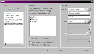
Given the number of interior elevations - types of elevations need to be isolated. As elevations are not view-dependant, there is a trick to isolate the categories you want. To isolate annotations- use filters in the visibility graphics for a view. Select a filter the uncheck the box under the View column. This will hide anything matching the filter. The default elevation style is now INTERIOR-INTR. There is also now an INTERIOR-ARCH. This controls the visibility of the system families symbols (the circles for the elevations as an example). When applying VIEW TEMPLATES consider whether you want to apply the V/G Overrides Filters - any pre-existing filters may be overwritten if this is checked- which is OK if that is what needs to be done to correct the view.

Revit Floor patterns and materials

Image
Kristine and I worked this out a little farther... Set the offset height when creating a new floor to 1/4" (element properties in the toolbar- not the option bar) and it will remain 'sticky' - i.e. upon finishing the floor, creating a new floor will retain that value. This offset allows shading of the materials to show when the plan is "viewed in shade mode with edges".. Different colors for the shading and surface patterns drive how the element displays- particularly the hidden line and shaded views. If the floors are co-planar (i.e. the offset is not set) materials will not tag correctly in plan(not even with tabbing.) and solid patterns get lost. (Note the solid hatch pattern + color will override the shading color!) Sheets can be created in color, and printed in either color or grayscale to easily identify layouts of materials on the floors- no more cryptic hatches! Maybe we should do a lunch and learn for this or a Revit session? The process has been revised

Using Revit with GlobalSCAPE WAFS

If you have been having trouble with linking, UNC paths and drive mapping this states the issues quite nicely and has a work aorund that may work: Using Revit with GlobalSCAPE WAFS Central File Access A single adjustment must be made on user workstations for users that will be working on work-shared Revit models being replicated by the WAFS system. The modification requires the creation of a new drive letter mapping using the Windows SUBST command. When Revit creates a Central file, it stores the path of the Central file within the Central file and associated local files. This path is used by the Revit workstations in conjunction with the local copies of the Central file to identify where the Central file resides for actions such as Save to Central, Reload Latest, and borrowing. When replicating Central files via the WAFS system, the Central files will be located on different file servers at each site. Thus, the UNC path will be different at each site and will result in Revit failing t

FW: DIMENSIONAL CLEANUP TRICK

Image
Rounding errors can be a problem which is why the smallest tolerance allowed is used. Typically when EQ./EQ. is used small fractions are created. Here is a trick to help cleanup the dimensions that aren't exact- Create a tolerance dimension style if it doesn't already exist. It should be labeled similarly to the original style- but suffixed similarly to "(1/8 TOL)". This is a *special* temporary dimension which reflects the tolerance bound within a particular dimension style(1/8" typically). If needed- create a continuous dimension string (Try to avoid individual dimensions if you can). You can select entire walls utilizing dimension options to define the 'how-to" for these strings and edit the witness lines as needed. Make a copy of the dimension string you want to correct. Change the copied dimension string to the tolerance style. The alternate string will show a rounded value closer to the correct tolerance: Cleanup by selecting the objects you wan